cb.web.local

A label stays on a product, but the information behind it can change

With TwinLead, Brady bridges physical markings with digital product data, turning a QR code into a permanent gateway to documentation, service, and compliance information.

From a Label to a Digital Access Point

The concept of a label is usually straightforward: it sticks to a product and displays information. But what happens when that information changes? This is precisely where Brady comes in with TwinLead. The software links physical identification markings with digital product data, turning an ordinary label into a lasting gateway to information, documents, and service offerings.

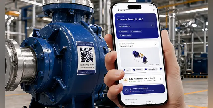
TwinLead is Brady’s Digital Product Platform. It links Brady labels to a cloud-based digital twin. Every appropriately labelled product receives a verifiable digital identity that can be accessed with a smartphone via a QR code—no additional app required.

The decisive difference compared to traditional identification lies behind the QR code. Printed information is permanent once the label is applied. By contrast, the digitally hosted contents in TwinLead can be updated at any time.

This becomes particularly compelling for products that remain in service for years. Operating manuals, technical specifications, and compliance details no longer need to remain locked to their production-day status. Companies can update the stored data while the original label stays on the product.

With a single scan, users can retrieve product specifications, manuals, videos, or support resources. Direct service requests, spare part orders, and repeat purchases can also be tied directly to the respective product.

A QR Code Accompanies the Product

Setup is handled through a no-code platform. Companies first determine which digital information should be associated with an item. Product attributes and documentation can be maintained in a single central repository.

Next, TwinLead generates unique, serialized QR codes for individual product units. These can be incorporated into existing production marking workflows or pre-printed directly by Brady.

This ensures that not just an entire product line, but - if desired - each individual unit receives its own digital identity. The associated data can then be centrally managed and updated remotely.

New printing hardware is not strictly required. According to Brady, TwinLead works seamlessly with existing Brady printers and label materials. The QR code simply becomes part of the existing label layout.

Brady sees key applications across industries including electronics, manufacturing, EV and battery technology, energy and utilities, and field services.
Product Information Never Needs to Go Out of Date

This highlights Brady’s core objective with TwinLead. While a standard QR code often points only to a generic website, TwinLead goes a step further by connecting individual products permanently to a centrally managed digital identity.

Manufacturers can continue to maintain product data long after an item has left the factory floor. New documentation, revised notices, and supplementary information can be pushed out dynamically at any time.

For end users, the experience of accessing product information changes as well. Instead of searching for paper manuals or contacting customer support, users retrieve everything on demand directly at the point of use via the product marking.

Brady also highlights the ability to streamline customer support: answers to frequently asked questions, troubleshooting workflows, and deeper technical resources are readily accessible right on the asset.

In addition, there is the regulatory dimension. Brady points to emerging mandates such as the Digital Product Passport (DPP), the Packaging and Packaging Waste Regulation (PPWR), and Right to Repair initiatives. For the Digital Product Passport, TwinLead offers dedicated templates pre-configured with required fields such as manufacturer details, origin, compliance records, and certifications.

Enterprise-Grade Security and Infrastructure

Product and label data are hosted by default on infrastructure within the European Union. The platform also supports role-based access control and comprehensive audit logging.

With TwinLead, Brady expands its foundational identification portfolio into the digital realm. While the physical label remains anchored to the product, the data behind it continues to evolve—transforming a piece of labeling into an intelligent touchpoint connecting product, manufacturer, and user.

Watch the video and learn more on Brady’s website!

Brady Corporation in Africa
This email address is being protected from spambots. You need JavaScript enabled to view it.
www.bradysouthafrica.com

____________________________________________________________________
Links:
https://www.brady.eu/software/twinlead?sfdc=701UK00000moJS6YAM&utm_medium=web-advertorial&utm_source=achora&utm_campaign=pwid-twinlead&utm_content=twinlead


A drilling-fluid report can look acceptable while the solids-control system is underperforming

Mud weight, plastic viscosity and yield point may remain inside their target ranges. But those figures do not tell us how the condition was maintained. Was unwanted formation material removed, or was its effect repeatedly managed by adding more fluid and chemicals?

Where the problem begins

Every metre drilled generates rock that must be transported to surface. The objective is to remove unwanted drilled solids early, while protecting useful drilling-fluid components and recovering as much fluid as practical. If cuttings bypass a shaker, screens are damaged, flow exceeds available capacity or fine particles remain in circulation, more formation material enters the active system. Continued circulation and dispersion can make some of it harder to separate.

Low-gravity solids (LGS) must not be treated as another name for drilled solids. Depending on the mud formulation, LGS can include deliberately added bentonite and other low-density materials. Likewise, a retort solids reading is not a direct measurement of formation contamination. A useful assessment distinguishes unwanted drilled solids from weighting materials, other additives and dissolved salts, using the appropriate mud-testing calculations.

The report can hide the cost

Dilution is a legitimate part of drilling-fluid management. It is not, by itself, evidence of poor performance. The trap appears when repeated dilution compensates for solids that the surface system should have removed. Fresh base fluid or newly built mud may bring measured properties back into range, while drilling-fluid consumption rises and the underlying separation problem continues. The operation can end up paying twice: once to build replacement mud and again to manage the fluid displaced from the pits.

Because active tanks have finite capacity, additional mud may require a corresponding displacement or bleed-off. That stream can carry recoverable liquid, treatment chemicals and, in weighted systems, valuable weighting material.

Depending on reuse and waste-handling arrangements, it may also require storage, transport and treatment. More mud added does not automatically mean an equal volume disposed; the complete inventory and waste balance must be checked.

A simple calculation exposes the mechanism

Consider an illustrative, well-mixed, constant-volume system operated at a hypothetical 5% drilled-solids concentration by volume (not an operating recommendation). Suppose 1 cu/m of drilled rock solids reaches surface and none is mechanically removed. In an ideal steady-state bleed-and-feed balance, retaining the same concentration requires displacing 20 cu/m of mud containing 5% drilled solids and adding 19 cu/m of fluid free of drilled solids. The remaining 1 cu/m of volume comes from the incoming rock.

Now assume mechanical separation removes 60% of that incoming rock-solids volume before it enters the active mud, assuming negligible associated liquid loss for this comparison. Only 0.4 cu/m remains. On the same ideal basis, the corresponding displacement falls to 8 cu/m and clean-fluid addition to 7.6 cu/m. That is an illustrative reduction of 11.4 cu/m of clean-fluid demand for the same solids input and target concentration — not a field saving estimate. Real operations must account for fluid carried out with separated cuttings, other gains and losses, treatment materials, actual mud formulation and changing tank volumes.

Follow the solids, not the equipment count

A proper rig evaluation follows the entire path from flowline to final waste handling. Is all returning mud directed across effective shaker screen area? Are flow distribution, screen condition and bypass arrangements controlled? Do hydrocyclones and centrifuges receive the right feed under suitable operating conditions? Is the recovered liquid returned to the correct tank, and how much valuable fluid leaves with the solids discharge?

These are connected decisions. A screen that is too coarse may pass avoidable drilled solids. A screen that is too restrictive for the available capacity may cause flooding, bypass or excessive fluid losses. Finer separation is not automatically better when it sacrifices throughput or discards valuable mud components. Equipment must be evaluated as a system under actual operating conditions. More rock discharged at the shaker can be a sign of success, not a waste-management failure, when fluid losses are controlled.

Measure the consequence per interval

The mud report remains essential, but it needs a companion material balance. For a defined drilling interval, compare estimated drilled-rock volume with mechanically removed solids, correcting for retained fluid; record clean-fluid and whole-mud additions, transfers, pit changes and discarded mud. Check retort results and corrected solids fractions alongside rheology trends. Measure or estimate liquid retained on cuttings and reconcile waste movements with recorded treatment or disposal volumes.

Interpret the trend against hole diameter, penetration rate, formation behaviour, fluid type and changes in operating conditions. A higher addition rate during faster drilling does not alone prove a solids-control failure. Equally, a stable viscosity reading does not prove effective removal. Look for repeated combinations: increasing makeup volumes, higher discard rates, deteriorating solids quality and avoidable screen or separation losses.

The real performance question

The aim is not zero dilution or maximum dry-solids discharge at any cost. It is the lowest practical total cost and waste burden while maintaining the required fluid properties and protecting the well. That requires solids control, drilling-fluids control and drilling-waste management to be measured together.

Before approving another routine dilution, ask one operational question: what fraction of the drilled solids did we actually remove before they became part of the mud? The answer is often more useful than the mud properties alone. 

The article has been written by Othman Soliman, founder of SC DrillTech

A joint industry project involving 14 oil and gas operators, service providers and vendors has updated a recommended practice for electric intelligent wells

The Intelligent Well Interface Standardisation (IWIS) project is facilitated by OTM Networks, part of R&D consultancy Sagentia Innovation. IWIS was established to standardise aspects of intelligent well technologies enabling a level of interoperability between different vendors.

IWIS 2.0 updates the original recommendations to support growing use of advanced electric completions, which require higher power levels and more sophisticated integration with subsea control and communication systems. It introduces recommendations for power, communications and mechanical interfaces, alongside safety and redundancy considerations.

A central feature of IWIS 2.0 is the introduction of an IWE Interface Module, for supply by downhole equipment vendors. This provides a standardised package for the larger, high-power interface electronics required by advanced electric completions, while allowing greater design flexibility and simplifying integration and qualification.

OTM has facilitated IWIS since the initiative was established, with the latest update involving 18 months of collaboration.

“Creating common ground between operators and technology companies is really important,” says Shreekant Mehta, Senior Vice President, Energy Sector at Sagentia Innovation. “By working together, they have developed recommended practice that reflects the realities of intelligent well applications, technologies and operating environments. IWIS 2.0 will help reduce duplication and integration effort, providing a practical route for new intelligent well technologies to work within evolving subsea architectures.”

The updated practice is intended to inform future revisions to API 17F Annex G for electric completions. It has also been developed with the intent to align with Subsea Instrumentation Interface Standardisation (SIIS) Level 3, which is being updated to level 3.1 and will include T1L Ethernet communications.

Operators involved in the IWIS 2.0 project include AkerBP, bp, Equinor, Petrobras, Shell and TotalEnergies. Technology companies include: Baker Hughes, Emerson, Halliburton, Metrol, SLB OneSubsea, TechnipFMC, Teledyne and Weatherford.


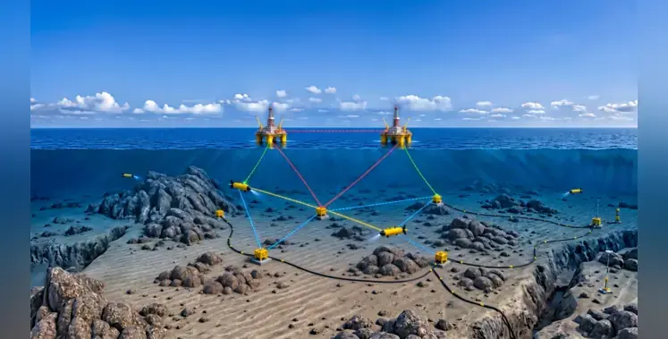
The new standard represents an important step towards optical modem interoperability for subsea systems. (Image source: SWiG)

Oil and gas industry network Subsea Wireless Group (SWiG) has released a new industry specification for free-space optical communications, providing a common protocol for modems from different manufacturers

SWiGoptical Level 1 defines a simple protocol to satisfy interoperability and interchangeability requirements for subsea free-space optical communication devices. It supports applications including, but not limited to, process control, equipment and process monitoring, diagnostics and maintenance, and data exchange and harvesting across autonomous underwater vehicles (AUVs) and other connected subsea systems.

Systems working together

SWiG, a joint industry project (JIP) managed by OTM Networks (part of R&D consultancy Sagentia Innovation), was established to enable vehicles, infrastructure and equipment from different suppliers to work together seamlessly. It has 27 members representing all parts of the supply chain, from major energy operators to subsea service providers and integrators to specialist instrumentation companies. Its objectives include:

• Promote interoperability between users of subsea wireless communications.
• Raise industry awareness and acceptance of subsea wireless communications.
• Identify areas (within subsea wireless communications) where open standards are needed, and develop them.
• Encourage the integration of subsea wireless communication technologies.
• Share best practices across the industry.
• Promote knowledge transfer across the industry.

Shreekant Mehta, senior vice president, Energy Sector at Sagentia Innovation, said SWiGoptical Level 1 represents an important step towards optical modem interoperability for subsea systems.

“SWiG’s goal is to create a common subsea ecosystem where devices from different manufacturers interact seamlessly,” Mehta explained. “As subsea communication technologies continue to mature, a collaborative approach to developing open standards supports cost management and provides a common framework, reducing deployment risk, simplifying integration and supporting scalability. Achieving interoperability across subsea operations is essential if the industry is to realise the full benefits of autonomy.”

The new specification builds on the earlier SWiGacoustic standard and is the latest in a family of complementary SWiG standards that also cover radio frequency (RF), inductive data and power and hybrid communications. SWiGoptical Level 1 is now available to the wider industry, with Level 2 and Level 3 specifications for higher-performance protocols already under development.

Oil and gas companies must build digital twins of whole systems when they have the money to do so. (Image credit: Siemens Digital Industries Software)

The oil and gas sector is hindered by legacy systems, overconfidence and stagnation

Now that the benefits of artificial intelligence (AI), digital twins and the industrial internet of things (IIoT) are mainstream, executives find themselves asking, “did we fall behind?” The answer is, yes.

MaKinsey Global Institute’s Industry Digitisation Index ranks the oil and gas industry slower to adopt data-centric technologies compared to leaders like banking, media and tech.

The oil and gas sector must act now

Oil is significant everywhere, not just energy and transportation. It’s needed to make fertilisers, food, chemicals, medications and plastics. The economy runs on oil and that will not change any time soon. Though this dependence shields the sector from disruption, it also breeds overconfidence.

During the pandemic we saw something bizarre: the price of oil going negative. The production of oil exceeded demand creating a surplus. Having run out of storage, some outlets were forced to pay others to take inventory off their hands. Geopolitical turbulences shot up prices. The recent price cycle proves a reality of financial strife for oil and gas companies. Therefore, they must act now, when margins
are high.

Imagine a scenario where oil prices drop below US$70 a barrel. At this threshold leadership embraces resilience and operational excellence strategies. They restrict capital expenditures and reduce operational expenses to profit with thinner margins.

When prices and revenue are high, like today, leadership tends to become less concerned about operational excellence. This is a myopic strategy. Resilience and operational excellence are important in high times as they help prepare for the worst times.

So, how do executives embrace resilience and operational excellence in times of high profit? It is not by tightening budgets. It is by investing in data strategies and digitalisation.

Learning from renewables

Consider the competition: renewable and nuclear power. They have limited time and resources to prove a project is profitable — be it solar, wind, geothermal, small modular reactors (SMRs) or fusion. They must make sure when they build a facility, or turn on a generator, that it works right the first time or risk running out of funds. They do this by embracing data strategies and digitalisation from the start. In this way, renewables leapfrogged the oil and gas sector — technologically speaking.

Digital twins, AI, IIoT are all used by renewable energy companies to reduce risk. They help them understand, predict and optimise assets before they exist. By bringing simulation and data analysis into the design, construction and operation of complex systems, they can identify problems, predict maintenance, troubleshoot and assess operational changes risk-free. Only when the data predicts success and regulatory compliance do they implement real world changes.

The key is to transform data into insights, and that’s not an easy thing to do — especially during lower margins. These insights, however, become more precious during those hard times as they help to maintain regulatory compliance and profitability. So, oil and gas companies must digitalise their processes and build digital twins of their entire value chain when they have the money to do so.

But where to start? Top priority must be to implement a data strategy that harmonises and contextualises the information into structures, ontologies and databases. This is because digital twins, AI and IIoT rely on quality and contextualised data to function. Next, make sure people in need of the data have access. Then, and only then, leverage the databases to build algorithms and AI models that simulate real world assets.

The article has been written by Thiago Ribeiro, global head of energy, chemicals and infrastructure at Siemens Digital Industries Software

More Articles …